What Is That
What Are Those?
In case you have noticed items on the electrical power grid and wondered what they are, this article should explain a few of them.
Dumbbells on Transmission Lines
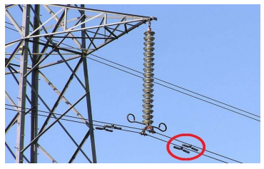
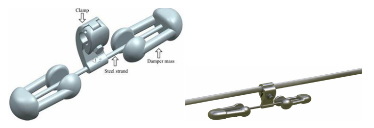
Stockbridge Damper for Transmission Lines
These dumbbell like devices are stockbridge dampers, invented by George Stockbridge in the 1920s. These dampen vibrations of the power lines, due primarily to wind. Without damping out these vibrations, the conductors would experience metal fatigue near the insulators and eventually fail, i.e., break. There are several designs of these dampers and alternatives that are less obvious to the casual observer. Stockbridge’s original patented design used cement blocks mounted on the ends of metal cables, while modern designs are entirely metal.
See https://en.wikipedia.org/wiki/Stockbridge_damper for a more detailed description ofstockbridge dampers.
There is another type of Stockbridge damper that is found on telephone cables. The placement of these dampers is generally at the center of the span between two telephone poles, rather than near a pole.
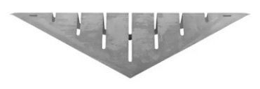
Stockbridge Damper for Telephone Cables
Rectangular Boxes on Power Poles
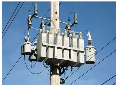
Power Factor Correction Capacitor Bank
These rectangular boxes are capacitors that perform power factor correction. The above photo show six capacitors, two on each of the three phases. As shown, these are often paired with round devices, which are switches used to remotely connect and disconnect the capacitors to or from the power distribution system, as needed.
Many of the devices that consume electricity, especially motors, draw current that is out of phase with and delayed slightly from the voltage. This results in a “lagging power factor” less than 1.0. A power factor less than 1.0, results in a higher current on the conductors and greater loss due to resistance of the conductors. The component of the current that is 90 degrees out of phase with the voltage is called a lagging reactive current.
Power=Voltage∗Current∗PowerFactor
A capacitor, on the other hand, draws a current that leads the voltage by a full 90 degrees and has a power factor of zero. This current is entirely a leading reactive current. If the lagging reactive current of the load is equal to the leading reactive current of the capacitor, power correction to as near to 1.0 as possible is achieved and the reactive currents flow only between the load and the capacitor.
Power factor correction is best done near the load, for the reason stated above, because a power factor close to 1.0 results in the least current on the conductors for the power consumed. This is why such capacitors are often seen on local distribution systems. However, they can also be located at a substation.
Industrial users are often penalized for having a bad power factor and, therefore, perform power factor correction on the customer side of the power meter. Residential users are not penalized for a bad power factor and the capacitors are located on the utility side of the power meter. Some residential loads that contain motors, such as air conditioners, will have internal capacitors, to improve their power factor and reduce current on the wires supplying these loads.
Since several articles on this web site mention the old 20 Hz power grid at Niagara Falls, I’ll just mention how power factor correction was performed on this grid. Capacitors are not very effective at this low frequency and another approach was used. An “over-excited synchronous motor” will provide a leading power factor and can therefore be used for power factor correction. Harper Station in Niagara Falls, N.Y. had three such machines, which were large motors with no shaft exiting the housing. They were large enough that a door-size hatch could be removed and a technician could step into the machine’s housing to perform maintenance. When operating, they were cooled and lubricated by pressurized hydrogen gas. After being evacuated, it took 14 welder’s tanks of hydrogen to pressurize the housing to 5 psi. The hydrogen gas was then water cooled.
Colored Balls on Transmission Lines
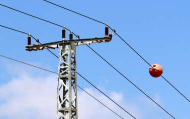
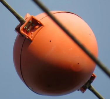
Visibility Marker Balls
These brightly (orange, yellow, or white) colored balls are called “visibility marker balls.” They help make power lines more obvious to low-flying aircraft such as planes and helicopters. They are usually seen near mountain passes, deep valleys, canyons, major freeway crossings, airports, dense forests, bodies of water, and other locations where aircraft tend to fly at low altitudes.
These balls are placed on the wire furthest from the ground, usually a ground wire, and are required on power lines more than 200 feet high. They are spaced not more than 200 feet apart and may be much closer together.
Some balls use the electric field of the power line to power LED lights that make them visible 24/7.
Colored Balls on Transmission Lines
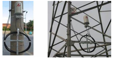
Power transmission lines make a great “right of way” fiber optic communications cables. These cables carry telephone and Internet data are are fastened to the ground conductor at the top of the tower. When junctions need to be made between spans of cable, the fibre optic cables descend the tower, form a loop and enter junction boxes mounted on the side of the tower.