Water and Ice Management
Treaty Between Canada and the United States of America Concerning the Diversion of the Niagara River, Oct. 10, 1950
Article II specifies remedial works (plastic surgery on the falls) to “produce an unbroken crestline on the falls, ” i.e., a continuous sheet of water flawing over the falls.
Article IV specifies the minimum amount of water over the falls for scenic purposes. Any amount of water flowing in the river above these amounts may be used for electric power generation. The flow of water is controlled by the International Control Dam, which is located entirely in Canadian waters. This average flow of the Niagara River is typically around 200,000 cubic feet per second
- 100,000 cubic feet (748.052 gallons, 2.832 ML) per second:
- Between 8 AM and 10 PM, April 1 through September 15
- Between 8 AM and 8 PM, September 16 through October 31
- 50,000 cubic feet (374,026 gallons, 1.416 ML) per second at all other times:
- Note: The treaty specifies Eastern Stand Time (EST), which has been amended to specify “local time,” so has to follow Daylight Saving Time.
Article VI states that the water available for power is divided evenly Canada and the United States. Canada has reversed the flow of some rivers, adding water to the Great Lakes system. This is Canadian water and Canada has exclusive use of that amount of water.
Article VIII states that if one party can not use their full share of water for power purposes, the other party may use that share. It has only been recently, since the completion of a second tunnel to the Sir Adam Beck facility that Canada has been able to use their full share.
Note: The treaty has been amended to say that the power generated using part of the other party’s share is generated on behalf of that other party and belongs to that party.
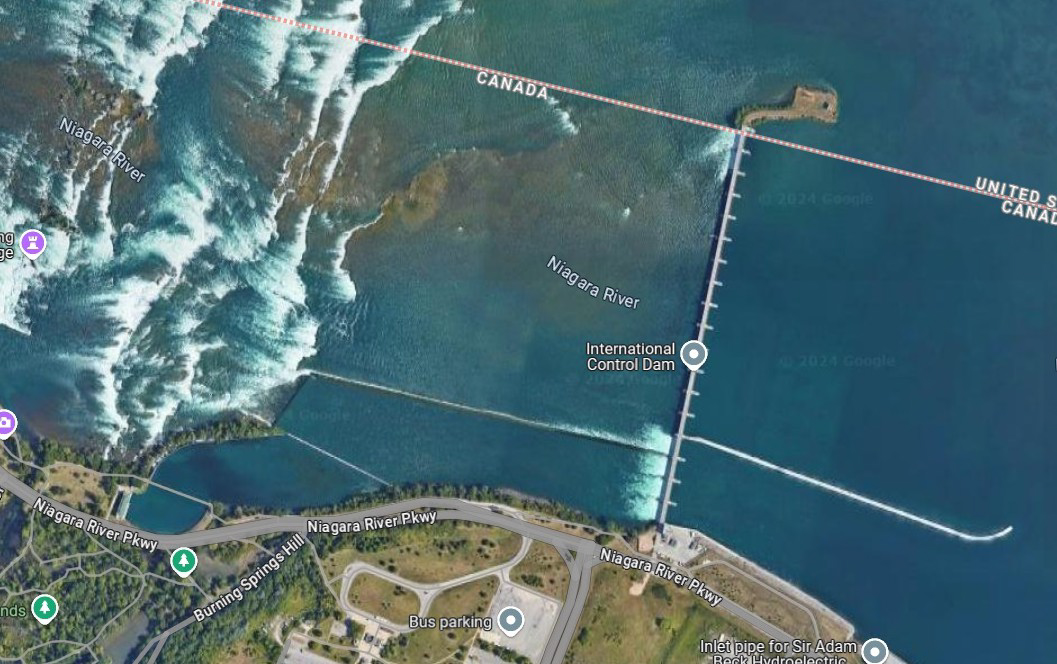
International Control Dam
Although not specified in the treaty, the distribution of water over the falls is as follows:
- 90% over the Horseshoe Falls, located almost entirely in Canada
- 9% over the American Falls, located entirely in the United States
- 1% over the Bridal Vale Falls, located entirely in the United States
Water Storage
The need for electric power increases during the afternoon, due to air conditioning and evening meal preparation and tapers off late in the late evening, as people retire. However, the availability of water is out of sync with the need for power. Therefore, both the Sir Adam Beck plant in Canada and the Robert Moses plant in the United State have large reservoirs for water storage.
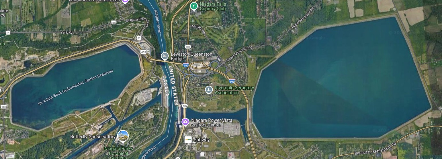
Sir Adam Beck (left) and Robert Moses (right) Reservoirs and Forebays
In the late afternoon as the demand for power increases, water is released from the reservoirs into the plants’ forebays. The pumps turn into generators, the water is returned to the forebay, and additional power is generated in the main part of the plant. During the late evening and night time hours, excess power is used to pump excess water up into the reservoirs, for use the following afternoon and evening.
Forebays and Surge Tanks
For each power plant there are protections that must be supplied for their water supply.
- Keep ice out of the penstocks and turbines.
- Allow generators to start up without starving other generators due to water supply
- Allow generators to shut down, while making provision for excess water flowing to the plant.
Keeping Ice Out
All water intakes draw water from below the surface, allowing any floating ice to simply float past the water intake. This is true of both power plants located on the river and power plants with intakes located on the river, some distance from the plant. Both the John Burch Rankin and Toronto Power plants, both in Canada, are on the river, allowing ice to simply float past the intakes. The Rankin outer forebay is the best depiction of this, as ice and water enter at one end of the forebay and ice floats out the other end. Water is drawn through arches below the wall of the building into the inner forebay.
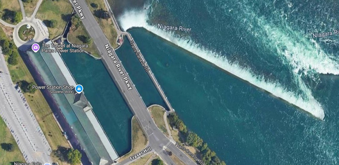
Rankin Outer Forebay
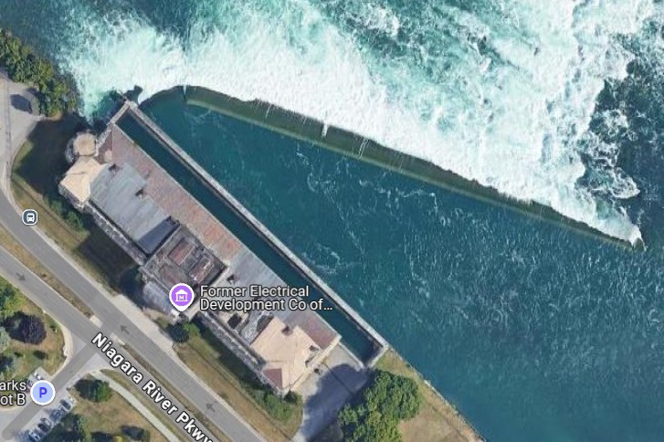
Toronto Power Outer Forebay
Surges and Starvation
These topics do not apply to the two power plants shown above, because they are directly on the bank of the river. However, other power plant have long canals (Scheollkopf), tunnels (Sir Adam Beck), or conduits (Robert Moses) supplying water the plant. The water in these supply paths has significant momentum and the flow can neither increase nor decrease rapidly enough to prevent surges or starvation. This is where the forebay provides buffered storage capacity
- When a generator starts up, there is not enough water flowing into the facility to prevent starvation of the generators already running. Water is temporarily drawn or borrowed from the forebay, until the flow into the forebay increases to a new, higher, and steady-state rate.
- When a generator shuts down, there is now too much water flowing into the facility, that needs somewhere to go or a surge will occur. The excess water is then temporarily stored the forebay, until the flow into the forebay decreases to a new, lower, and steady-state rate.
One of the most interesting designs is the Ontario Power plant, located at the bottom of the Niagara Gorge, in the heart of the park’s tourist area. There simply is no room for a forebay. The entire water supply system from the intake up-river to the plant, consisting of three conduits, is located entirely below ground. A surge in this water supply system would blow up the roadway going through the park. The solution here is a surge tank, located on the opposite side of the roadway. (The lights that illuminate the Horseshoe Falls at night are mounted on the top of a side building of the surge tank.) From the ground, the surge tank looks like a vine covered, windowless building with a pipe coming out of its side. From above, it has no roof and the surge pipe coming up into the center of the tank is clearly visible. The pipe coming out the side drains the water back into the lower river.
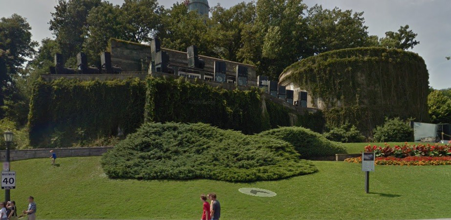
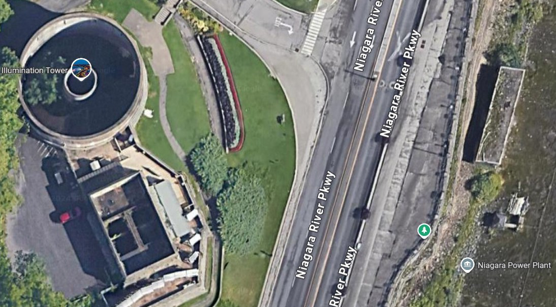
Ontario Power Surge Tank
The Lake Erie Ice Boom
The geology of the region, results in some very interesting results regarding Lake Erie. Lake Erie is a very shallow lake, which contributes to the following:
- In Summer, Lake Erie heats up, because of its shallowness
- From around mid-November to some time in January, cold Winter winds come down from Canada, pick up a lot of moisture from the warm lake and bury Buffalo in snow.
- Some time in January or February, Lake Erie usually freezes over and the snow ceases. The ice can be up to 12 feet thick. (Climate change is altering the timing and may prevent Lake Erie from even freezing some years.)
- In Spring, the ice breaks up and is forced toward the entrance of the Niagara River by both wind and water flow.
If large amounts of ice are allowed to flow down the Niagara River it can cause a glacier-like blockage of both the upper river, above the falls and the lower river, below the falls. A blockage above the falls can entirely block the outflow of the Great Lakes, cause flooding, property damage, shoreline damage and jamming the water intakes of the hydroelectric plants. The solution is to install “the boom” which is installed in December and removed between early March and early May, after the ice is sufficiently thawed. As shown in the photo below, the boom creates an “ice arch,” preventing ice flows from the lake in the Niagara River.
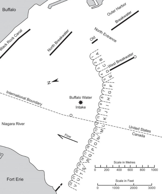
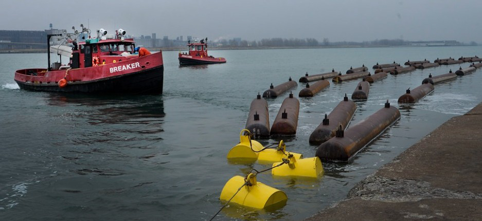
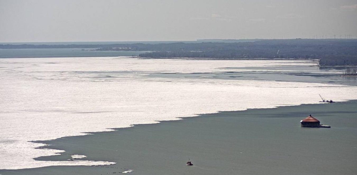
The Lake Erie Ice Boom
As shown in the diagram above, the boom consists of 22 spans and is 8,800 feet in length. The first four spans are constructed with 16, 15-foot long pontoons. The remaining 18 spans are constructed with 10 pontoons, each 30 feet in length and 30 inches in diameter. The spans are anchored at 400 foot intervals to the lake bottom with 2.5 inch steel cables. Initially, the boom was constructed from timbers/logs, which is what I remember. It was converted to steel pontoons for the 1997-1998 Winter. Even with its strength, wind-driven ice can break the boom in some Winters. The boom is jointly owned and operated by the New York Power Authority and Ontario Power Generation.
The Big Boom Fiasco
For decades, the local power company, the Niagara Mohawk Power Corporation (my Father’s employer) managed the annual installation and removal of the boom. When the Robert Moses power plant came on line in 1961, the New York State took control and contemplated whether or not the boom was really necessary. Like good engineers, this is when you build models and run simulations.
An engineering company in the Southern United States was contracted to do the investigation. They built a room-size scale model of the Niagara River. For ice, they used something that looked like ice and floated like ice, blocks of paraffin wax. As a high school senior at the time and future engineer, even I knew this simulation was bogus. My father and I just laughed, because we knew what would happen.
- If you slam two pieces of paraffin wax together in water, what happens? Nothing. You still have two pieces of paraffin wax.
- If you slam two pieces of ice together in freezing water, what happens? You will have one large piece of ice.
- A model or simulation must reflect reality. Paraffin wax does not emulate ice!
With the results of this simulation, the State decided that the boom was not necessary and did not install it for the 1961-1962 Winter season. In the Spring, the upper river was completely jammed by a glacier of ice, blocking the river and the intakes to the new power plant. They had crews with rock drilling rigs boring holes for dynamite to break up the ice. After the broken up ice went over the falls, it formed another glacier in the lower river, one much larger and thicker than what normally forms. I remember going down to the lower river in Lewiston, NY and seeing a huge wall of ice, slowly moving past me. Many well-off people had boat houses and boats in the lower Niagara River, past the rapids. They were ground to pieces and carried out into Lake Ontario. The cost of this poorly informed decision to not install the boom was enormous. The next Winter, the boom was back in use.