Excessive Neutral Current in Three Phase, Wye-Connected Systems
Introduction
While there are a few papers available on the Internet discussing the issue of excessive neutral current
in wye-connected three-phase systems, few give a complete understanding of the problem.
Furthermore, the vase majority of electricians and the standards fail to grasp the issue. With
incandescent light bulbs, linear loads, vanishing and more other lighting technologies and electronic
(non-linear) loads becoming dominate, the issue is becoming more relevant. The result is dangerously
excessive current on the phase systems and “home runs” with a common the neutral wire.
- Early in my career as an electrical engineer, I was summoned by the electricians in a large commercial building. They had carefully balanced the current in all three phases, each supplying a number of 120 Volt fluorescent lighting fixtures. They questioning why the neutral conductor of the same gauge was so hot that the insulation was visibly smoking, when they thought at the neutral current should be nearly zero.
- Late in my career, I wired an office building under the direction of a licensed electrician. He would run a 12/4 AWG three phase “home run” from the breaker panel to the office area and put circuits containing about 1/3 of the 120 Volt fluorescent lighting fixtures on each phase. When I challenged him about the current on the 12 AWG neutral wire, he told me that I didn't know what I was talking about. He completely discounted by educational credentials and experience.
- While working as the liaison between a lighting contractor and an electrician, I was told by the lighting contractor to require separate neutral wires for each phase. The electrician didn't understand or agree, but did what we asked and paid him to do. This paper explains why this was required.
- The two technical papers that I have found on the subject are held by the Institute of Electrical and Electronic Engineers (IEEE) and are unavailable to non-members of the IEEE. They are also more technical, with standards setters being the primary audience. Therefore, I felt that a public domain paper, intended more for electricians, is needed.
- In talking to many electricians, all but one were taught and firmly believed that the neutral current on a balanced three phase, wye-connected system will be zero and a neutral wire of the same gauge as the phase wires is sufficient, appropriate, and standard. The one exception simply and correctly said; “The neutral current could be as high as 1.73 times the phase current.”
- The loads are balanced, i.e., the same current exists on each of the three phases.
- Most importantly, the loads are linear, i.e., the currents are sinusoidal, just as the voltages are sinusoidal. However, this is seldom the case with modern fluorescent or LED lighting and electronic loads. Of the lighting technologies, only incandescent bulbs are linear. Resistance heating devices are the only other linear loads.
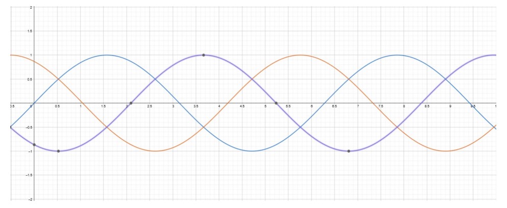
- The loads on each phase is of the same power factor, i.e., the sinusoidal currents are 120 degrees apart, just as the voltages are 120 degrees apart.
Ammeters
Effects of Non-Linear Loads
Stell, MSEE, BS(EE) 2 of 6 02/02/20, updated 01/29/26
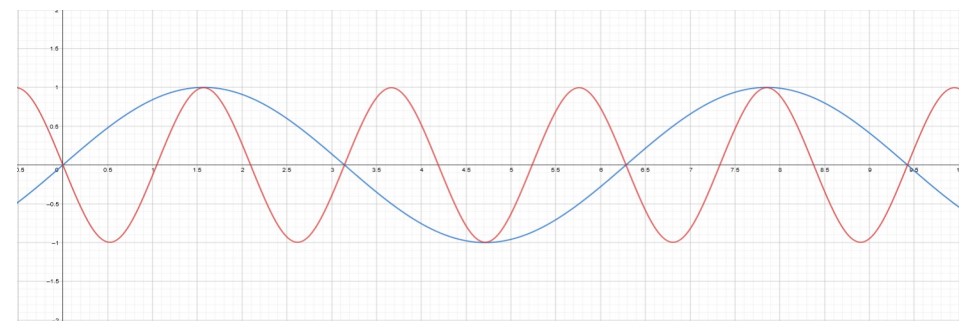
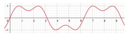
The graphic below shows the neutral current for a relatively small degree of non-linearity in the loads. The voltage on one phase is shown as a horizontal reference. Note that the current is entirely third harmonic current, 180 Hz, with no 60 Hz component. Again the magnitude is scaled to the range of -1 to +1. Even with this small degree of non-linearity, the neutral current was approximately equal to the per-phase current.
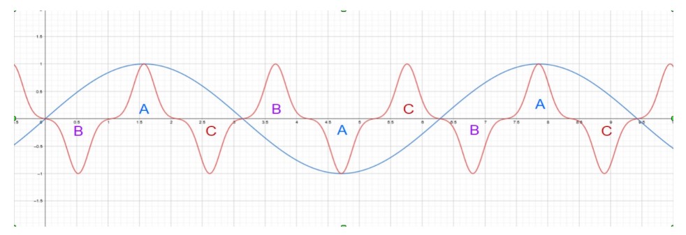
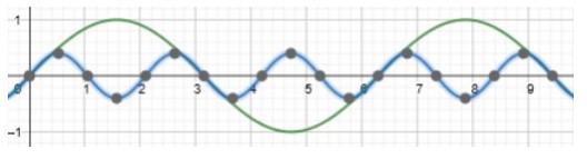
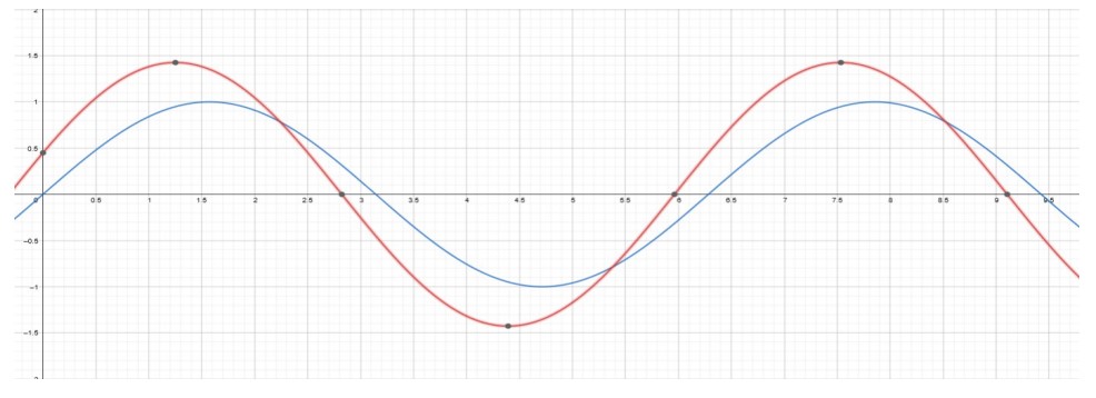
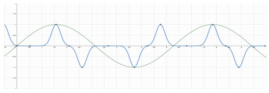
Note: There are Internet videos showing 1st and 3rd harmonic currents like those on the right, with the combined current shown at the lower right. However, these scenarios apply to specific loads, such as variable speed drives (motors). These loads are not the subject of this paper. The waveform above simulates and is more typical of modern lighting and electronic loads.
Effects of Differing Power Factors
RV or Apartment on 2 Phases.
NFPA 70: 2020 National Electrical Code
- (1) A neutral conductor that carries only the unbalanced current from other conductors of the same circuit shall not be required to be counted when applying the provsions of 310.15(C)(1).
- (2) In a 3-wire circuit consisting of two phase conductors and the neutral conductor of a 4-wire, 3-phase, wye-connected system, a common conductor carries approximately the same current as the line-to-neutral load currents of the other conductors and shall be counted when applying the provisions of 310,15(C)(1). (Note: the neutral current can be up to 1.4 times the current on the other conductors.)
- (3) On a 4-wire, 3-phase wye circuit where the major portion of the load consists of nonlinear loads, harmonic currents are present in the neutral conductor; the neutral conductor shall therefore be considered a current-carrying conductor. (Note: the neutral current can be up to 1.7 times the current on the other conductors.)
Third Harmonic Current Elimination
- Delta connected three-phase transformers. A delta-connected primary on the utility side and a wyeconnected secondary on the customer side is sufficient.
- Use of a Zig-Zag configuration using three transformers or extra windings within a three-phase transformer. These are also used to provide a virtual neutral and ground fault detection in delta connected systems. A virtual neutral prevents a delta-connected systems voltage from drifting away from ground and blowing out cables.
- Active filters, which tend to be expensive and less reliable than transformers.
Conclusions and Recommendations
- The standard logic, taught to electricians, regarding neutral current is wrong and should be amended.
- The accepted practice and codes requiring that the neutral conductor need be only of the same gauge as the per-phase conductors is dangerously wrong and can result in a burnt or open neutral. The consequences of a burnt-open neutral can be catastrophic. These practices and the NEC have been amended to require either of the following, which addresses the problem without the need for detailed understanding by members of the trade:
- Separate neutral wires of the same size for each phase.
- 3-phase: A single neutral wire of sufficient gauge to carry 1.70 ( √(3)=1.732 ) times the perphase current could be used. This equates to 4 AWG sizes larger than the per-phase wires. For example, my 20 Amp, 12 AWG lighting case, would require an 8 AWG neutral wire.
- 2 of 3 phases (Apartment or RV cases): A single neutral wire of sufficient gauge to carry 1.40 ( √(2)=1.414 ) times the per-phase current could be used