What Type of Power
Alternating Current (AC) versus Direct Current (DC)
Direct Current (DC)
- Power must be generated, distributed, and consumed at the same voltage, since there was no practical way change the voltage/current relationship.
- This made transmission and generator wires huge.
- Transmission was limited distances to the order of on city blocks or two miles, maximum.
- Neighborhood generating station were necessary, making DC power practical only in densely populated cities, such as lower Manhattan.
Alternating Current (AC)
- Power can be generated, distributed, and consumed at different voltages, since transformers can easily change the voltage/current relationship. Higher voltages are used for transmission and lower voltages for consumption.
- Transmission, generator, and consumer wires can be different and more reasonable sizes, simply by using higher voltages to transmit higher power levels.
- Transmission distances are no longer limited and can be many hundreds of miles.
- Much larger regional generating stations are now possible.
- The Adams Power Plant generated power at 2,200 volts. Transformers then raised the voltage to 11,000 and later 22,000 volts for long distance transmission at lower current.
- Robert Moses Power Plant generates power at about 13,200 volts and enormous current. It is immediately raised to 115,000 volts and much less current to transmission to the distribution facility. From there, power is supplied near and far at 115,000, 230,000, and 345,000 volts.
Two-Phase Versus Three-Phase
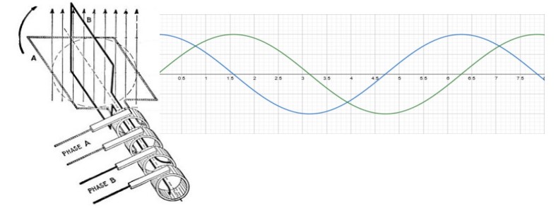
Two-Phase, Four-Wire Generation and Waveform
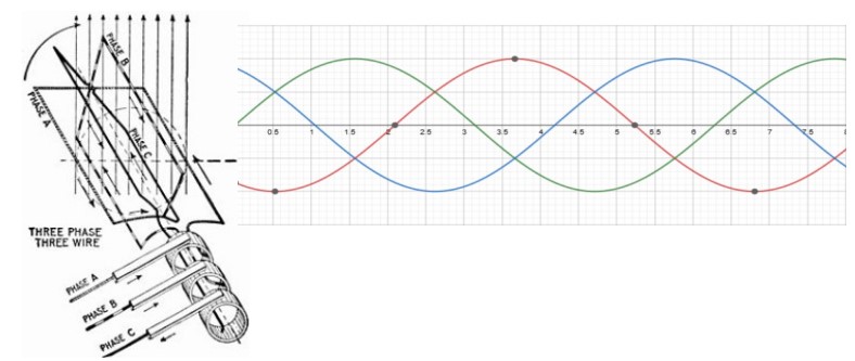
Three-Phase, Three-Wire Generation and Waveform
Next came the problem of how to interface the two-phase generators to Tesla’s new three-phase transmission system. Wikipedia has a great description of the Scott-T Transformer configuration used for this purpose. See: https://en.wikipedia.org/wiki/Scott-T_transformer. This configuration uses a bank of two transformers with specific winding ratios to convert between the two systems, as shown below from the Wikipedia article. The “T” in the name becomes obvious when the transformer windings are shown according to their vector orientation, as shown in the diagram. Winding R1-R2 is connected to one phase of the generator’s output and winding R3-R4 is connected to the other phase of the generator’s output. The three-phase transmission line is connected to the Y1-Y2-Y3 terminals. Although now shown, there can also be a “virtual neutral” tap, below Y1, which is useful for several purposes.
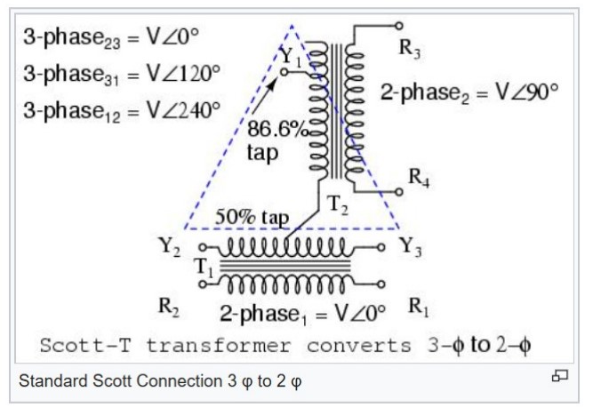
Scott-T Two-Phase to Three Phase Conversion Confiuration
Frequency
- Civil War era textile factories typically generated power at 40 Hz.
- Manhattan initially generated only DC power and did so until 2007.
- Switzerland still operates a 16.7 Hz nation-wide grid for its electric trains. (The trains can usually also operate on 50 Hz for trans-border use.)
- Power at Decew #1 in St. Catherines, Ont. Was initially generated at 66.66 Hz.
- Power at Niagara was initially generated at 0 Hz (DC), 25 HZ, 60 Hz and 115 Hz.
- Power at Niagara then standardized on 25 Hz, which was used by industry in both countries and used for residential power in Canada, but not the U.S..
- Power at Niagara was later generated at both 25 HZ and 60 Hz and now only 60 Hz.
- Europe and other parts of the world standardized on 50 Hz.
- North America and some parts of the world standardized on 60 Hz.
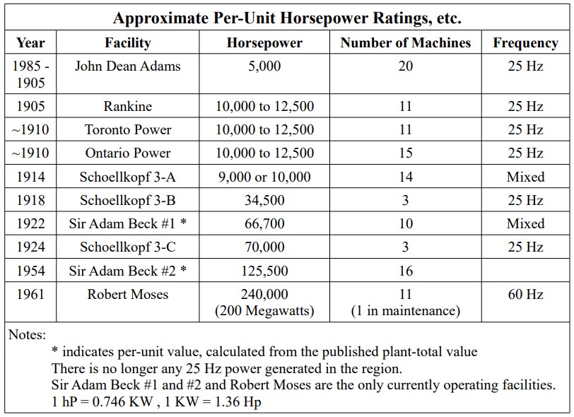
- John Dean Adams, John Birch Rankin, Toronto Power, Ontario Power, Schoellkopf 3-B, and Schoellkopf 3-C generated only 25 Hz power.
- Schoellkopf 3-A and Sir Adam Beck generated both 25 Hz and 60 Hz power.
- Sir Adam Beck in Canada, the Huntley (steam) Generating Station in Tonawanda, N.N., and the repurposed (post-1940) John Dean Adams Transformer House had 60 Hz to 25 Hz frequency converters.
Moving power between the 25 Hz and 60 Hz grids
- Two 60-to-25 Hz machines were installed in the Adams Transformer House, after the transformers were scrapped, around 1940. A third was added in the 1960s. These were owned by Union Carbide, operated by Niagara Mohawk, and powered metallurgy furnaces in Niagara Falls, N.Y.. These machines were automatic and required an operator only to put them on-line and take them off-line.
- At lease one other 60-to-25 Hz machine existed at Sir Adam Beck #1.
- A 25-to-60 Hz also existed in Lockport, N.Y
Changing the frequency generated by a generator
- Gross adjustment: The winding/poles of the machine would be removed and replaced by a new and different number of windings/poles. The number of poles is determined by the frequency desired and the rotational speed for which the turbines were designed. The goal is to get as close to the desired frequency as possible, at the design speed.
- Fine adjustment: The speed of the turbine and generator would be altered to obtain the correct frequency. A different turbine, designed for the new rotational speed may also replace the old turbine.
Size Matters
References
- 25-Hz at Niagara Falls, end of an era on the Niagara Frontier, parts 1 & 2, IEEE power & energy magazine, January/February 2008
- Niagara Falls History of Power, http://www.niagarafrontier.com/power.html
- Rankine Generation Station, 100 Years of Power Generation, Professor Mark Csele, http://www.technology.niagarac.on.ca/people/mcsele/interest/rankine-generating-station/