Terminology
This article describes terms that are generic to multiple power plants, rather than specific to any one facility.
Hertz
The English term Cycles per Second (CPS) was renamed Hertz (Hz) in 1960 in accordance with the International System of Units. The new name is in honor of the Germany physicist Heirich Hertz.
CPS or Hz refers to the number of oscillations per second. In the case of electrical power, it is the number of full sinusoidal voltage variations per second. While most of the world is now standardized on either 50 Hz or 60 Hz, the original, pre-grid frequency in the Niagara region was 25 Hz, set in 1895 by the John Dean Adams plant.
Horsepower vs. Kilowatts
Generatots are rated in either horsepower or kilowatts. Horse-power to/from Kilowatt conversion: 1 Hp = 0.746 kW conversely 1 kW = 1.341 Hp (This is English mechanical Hp, which is slightly different from metric Hp and electrical Hp.)
Penstock
This term is used for the pipes that carries water for the source at the top, the forebay, to the turbines at the bottom of the power plant.
Tailrace
This term is used for the cavity below the turbine into which the water flow from the turbines. One major purpose of the tailrace is to stop the rotational flow of the water exiting the turbines. The best place to see tailraces at Niagara Falls is the ruins of the Schoellkopf 3A facility.
Head
For a hydroelectric plant “head” is defined as the vertical distance between the water source at the top and the turbine at the bottom. The extractable amount of power per unit of water is directly proportional to the “head.”
One of the most common questions asked is; “Why are the modern power plants located so far down river, rather than at the falls?”
A private pilot once defined “waste” as “runway behind you and altitude above you.” The equivalent waste for a hydoelectric plant is “elevation change below the turbine.” Three examples will explain perfectly.
- The Adams power plant was located 1.25 miles up-stream from the falls. As a result, it had to sacrifice 80 feet of available elevation change to create a proper slope for its 7,500 foot long discharge tunnel. Therefore, Adams had a “head” of only 140 feet.
- The next generation of power plants were located near the falls, where the discharge tunnel was either much shorter or nonexistent. Therefore, most or all of the 80 feet below the Adams turbines could now be above the turbines. These plants had “heads” of 200 +/- about 10 feet.
- Taking this one step further, the lower Niagara River is mostly rapids from the Rainbow Bridge to just in front of Niagara University in Lewiston Heights. That accounts for about another 80 feet of elevation change. Therefore, the modern power plants can now have most or all of the 80 feet of the river's descent above the turbines. These plants have “heads” of around 315 feet.
There is only a very short span of the Niagara River where the vertical elevation change and, therefore, a hydoelectric plant’s efficiency is maximized. This after the rapids, just North of Niagara University and before the Niagara Escarpment, where the land drops dramatically. Therefore, the Sir Adam Beck #1, ir Adam Beck #2, and the Robert Moses power plants are all located location.
“Station Power,” “House Power,” and “Black Power”
“Station Power” and “House Power” are synonymous. They refer to the electric power required to operate the power plant. Before we had the “grid” or before the grid was a trusted source of power, plants often had small, manually operated generators that supplied enough power to operate the control systems of there main generators. These were called “Station Power” and “House Power” machines.
“Black Power” is a form of “Station Power” or “House Power” that is intended to provide start-up power in the event of a “black out” and total loss of available power from the grid. The sources could be manually operated hydroelectric generators, diesel generators, dedicated transmission lines from other facilities that can restart on their own, or a combination of these sources. Hydroelectric plants only need black power for a short time to get the main generators running. Steam plants, whether fossil fuel fired and nuclear, require power for days in order to boil water and make steam. The largest nuclear plant in the United States can rely on a hydroelectric plant on the Colorado River as its source of black power. That hydroelectric plant has “Station Power” and “House Power” machines to get itself up and running, in order to provide power the the nuclear plant, via a dedicated transmission line.
The industry had a rude awakening during the great Northeast Blackout of 1965. Modern power plants, such as Robert Moses had come to rely on the grid, which suddenly was no longer there. It took several days of highly coordinated effort to get all of the power plants back up and running, Robert Moses now has a diesel, which probably has not been needed since it was installed. Most likely, the 1965 lesson prompted other power plants to rethink the reliability of the grid and make similar provisions.
Dual Runner Turbine
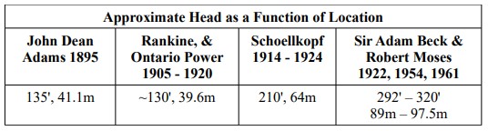
The literature refers to some generator plants having “dual-runner” turbines, which may sense for a steam turbine, but not for hydroelectric turbines. A better term in this case would be “dual turbines” or “twin turbines.” The reason for this design is that a turbine is generally larger than its mated generator of the same horsepower. The choice is to either make the building larger to house the single turbine or use two smaller turbines on the same shaft and driving the same generator. The photo of the Ontario Power Plant shows two turbines on the left, the main generator in the middle, and the exciter on the right. According to the drawings, the Adams power plant also used dual turbines, one above the other, but photographs of these turbines seem to exist.
Ontario Power Plant Interior Twin turbines – Main generator – Exciter
Exciters and Excitation
Excitement refers to the source of the Direct Current for the field windings of the generator. This too has evolved over time. The output of the main generator is partly controlled by its field current and output of the exciter, which is controlled by the operator. This has an amplification effect, where a small knob controls a large machine.
- The Adams Power Plant utilized several DC generators, called exciters, belt driven off the main generator shaft. They were located on a deck just below the generator and just above the thrust bearing deck.
- Later generators, such as seen in the Toronto Power, Rankine, Ontario Power and Schoellkopf power plants have exciters that look like warts on the shaft of the main generator. These are usually small DC generators, mounted on the end of the main generator's shaft, as can be seen in the photo of the Ontario Power Plant, above. For vertical shaft generators, the exciter is mounted on the top of the main generator.
- The John Birch Rankin power plant used separate motor/generator machines as exciters, physically separated from the main generators. Since this is now a museum, they can be seen by the public and the shell of one is located outside the museum.
- Today, modern plants use high-power, solid-state rectifiers, thereby eliminating the need for mechanical exciters and increasing reliability of the system.
- There are also designs that integrate the exciter and rectifier functions with the main machine, thereby eliminating the need for any failure-prone comutators, slip rings, and brushes.
In some cases, the exciters are merely mechanical rectifiers made up of commutators and brushes, but no windings. Residual magnetism in the main generator’s field windings will enable the generator to produce a little output, which can be rectified and fed back into the field windings. In the case of these exciters, they must be mounted on the main generator’s shaft, so as to maintain synchronization with the generator’s output.
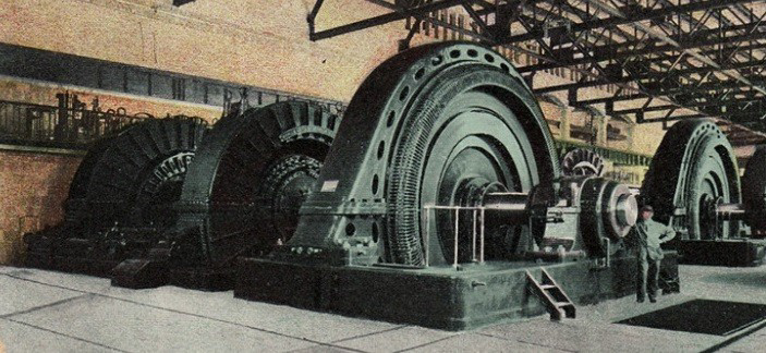
Deep Pit Design
Of all the generating plants at Niagara, only three are of the “deep pit” design. These were the Adams, Toronto Power, and Rankine Power Plants. In this design, the generators were located at ground level, near the source of water. The turbines were located at the bottom of a deep pit, directly below the generators. Water flowed down to the turbines through pipes, called penstocks. The mechanical energy produced by the turbines flowed up to the generators above via very long, vertical shafts. This design would be totally impractical for larger generators, due to the weight of the shaft to be supported by a single thrust bearing.
This design is also plagued by the fact that the rock layers shift over time, making it necessary to move the turbines back into alignment with the generators above. By the ends of its life in 2008, Rankine station had exhausted its ability to realign it turbines with its generators.
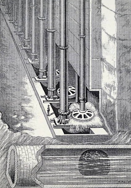
Deep Design Wheel Pit & Discharge Tunnel
Thrust Bearings and Thrust Deck
Of all the generating plants at Niagara, only three are of the “deep pit” design. These were the Adams, Toronto Power, and Rankine Power Plants. In this design, the generators were located at ground level, near the source of water. The turbines were located at the bottom of a deep pit, directly below the generators. Water flowed down to the turbines through pipes, called penstocks. The mechanical energy produced by the turbines flowed up to the generators above via very long, vertical shafts.
The entire weight of the rotating part of the generator, the long shaft, and the turbine rested on a single, bulbous “thrust bearing,” located on the “thrust deck,” below the generator. Lubrication and cooling of the oil-filled, water cooled thrust bearing was a major concern, as was the energy lost in the bearing due to friction. Strangely, the bearing surfaces were often made of a soft metal, called “babbitt” and/or teak wood. This design is hard to imagine for these generators in the 5,000 to 12,500 Hp range. Extending this design to larger machines defies logic.
Oil and cooling water for the thrust bearing required a back-up system that allowed the machine to be shut down, without damage to the bearing, in the event an oil or water pump failed. One plant had roof mounted oil and water tanks and another had tanks mounted on a near-by hill.
One might wonder about mechanical stability and wobble in a mechanical configuration of this length. Wobble was controlled by several “guide or collar bearings” along the shaft. Stability, as it relates to movement in the rock layers, proved to be problematic at the end of Rankine Station’s long life. The turbines had been moved about as far as possible to maintain proper alignment with the generator above.
The obvious solution to this weight and bearing problem is to shorten the shaft by moving the generator down to a location only slightly above or next to the turbine. This was accomplished by building the other power plants either at the bottom of the Niagara gorge or into the side of the gorge. The Schoellkopf 3-B and 3-C power plants had short vertical shafts with the turbine(s) located below the generators. The newer power plants have short vertical shafts with the turbines located just below the generators.
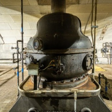
Rankine Station's Thrust Bearing
Modern vertical shaft power plants use pressurized water to support the weight, thereby eliminating the environmental concern associated with lubricating oil leaks.